Antenna Systems can make or break an wireless system installation. The engineers at Professional Wireless Systems can assist you in determining the best antenna and cable foryourneeds. Below is a list of common antennas. Each antenna has it's own advantages and disadvantages. It's not really possible to say that any one antenna is best or worst. That determination can only be made on a case by case basis for each installation.
Other Accessories such as multicouplers, line amplifiers, passive combiner / splitters and filters are also part of the antenna system. Let PWS provide you with "Custom Solutions" for your installation. Entire installation packages are available on a custom designed basis.
Advantages
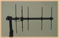
The Yagi-Uda Antenna is a widely used antenna design due to its high gain capability, low cost and ease of construction. It consists of a dipole arranged with various parasitic elements.
example:
 6 to 9 dbi gain
(depending on the number of elements)
Very wide bandwidth
(450 to 975 MHz for the model shown)
Typically 50° to 70° beam width
The "Log Periodic Dipole Array" is ideally suited for use with multiple receiver installations covering a wide band of UHF frequencies and where directivity, long range or back end rejection of interference is desired. Compare this antenna to a choir microphone.
 6 to 10+ dbi gain
(depending on the number of elements)
Narrow bandwidth
(506 to 536 MHz for the model shown.)
Typically 40° to 70° beam width
This antenna is ideally suited to installations in which the range of frequencies in use is fairly small. This antenna provides long range (from the front) and high rejection (from the rear). The tight RF bandwidth and narrow beamwidth of this antenna make it ideal for custom applications with high demand requirements. Compare this antenna to a shotgun microphone with a tight acoustic filter.
To get more advantages about Yagi Uda antenna.
Optimization of the Yagi-Uda Antenna can be achieved by simulating the radiation patterns for various lengths of the elemnets and the spacing between them. Other factors that effect the radiation pattern are:
For an antenna with a length of 6 wavelengths or more the overall gain is independant of the director spacing.
The reflector size and spacing have negligable effect on the forward gain and large effects on the backward gain and input impedance.
The size and spacing of the directors has a large effect on the forward gain, backward gain and input impedance.
More than one reflector provides little improvement on the directivity of the antenna.
The addition of more directors will increase the gain of the antenna although after the addition of approximately 5 directors the advantages of adding more directors decreases significantly.
The use of a folded dipole will increase the input impedance of the driven element. This is an advantage as the Yagi design generally has a low input impedance and the antenna impedance needs to match the transmission line impedance.
Disadvantages
Generally, receiver of yagi uda antenna having some problem in receiving the signal. The function of these elements is to enhance the radiation pattern in the source direction. The reflector will be 5% longer than the driven element (ie diploe)and the directors will be 5% shorter. Parameter limits are:
-Driven Element only produce about 0.45-0.49 wavelengths.
-Directors also can provide only 0.4-0.45 wavelengths.
-Separation between Directors only have 0.3-0.4 wavelengths.
-Radiation of directors is 0.15-0.25 wavelengths.
-Separation between driven element an parasitics only 0.15-0.25 wavelengths.
No comments:
Post a Comment