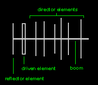
THE DRIVEN ELEMENT
A dipole driven element will be "resonant" when its electrical length is 1/2 of the wavelength of the frequency applied to its feed point.
The feed point in the picture above is on the center of the driven element.
THE DIRECTOR
The director/s is the shortest of the parasitic elements and this end of the Yagi is aimed at the receiving station. It is resonant slightly higher in frequency than the driven element, and its length will be about 5% shorter, progressively than the driven element. The director/s length/s can vary, depending upon the director spacing, the number of directors used in the antenna, the desired pattern, pattern bandwidth and element diameter. The number of directors that can be used are determined by the physical size (length) of the supporting boom needed by your design.
The amount of gain is directly proportional to the length of the antenna array and not by the number of directors used. The spacing of the directors can range from .1 wavelength to .5 wavelength or more and will depend largely upon the design specifications of the antenna.
THE REFLECTOR
BANDWIDTH AND IMPEDANCE

The impedance of an element is its value of pure resistance at the feed point plus any reactance (capacitive or inductive) that is present at that feed point. Of primary importance here is the impedance of the driven element, the point on the antenna where the transfer of rf from the feedline takes place.
The impedance bandwidth of the driven element is the range of frequencies above and below the center design frequency of the antenna that the driven element's feed point will accept maximum power (rf), from the feedline.
The design goal is to have the reactance at the center design frequency of the Yagi = (0),,, (j + 0).
The impedance matching device will now operate at it's optimum bandwidth. Wide element spacing, large element diameter, wide pattern bandwidth, and low "Q" matching systems will all add to a wider impedance bandwidth.
ABOUT ANTENNA PATTERNS

The antenna's radiation pattern or polar plot as it is sometimes called plays a major role in the overall performance of the Yagi antenna.
The amount of variation from the antenna's design specification goals that can be tolerated is subjective, and limits put into the design are mainly a matter of choice of the designer. "In other words.....trade offs".
Wide spacing will increase the bandwidth, but the sidelobes become large.
By varying both the spacing and director lengths the pattern and the pattern bandwidth may be more controlled.
More directors within a given boom length won't increase the gain by any great amount, but will give you better control of the antenna's pattern over a wider range of frequencies in the band of design.
If you reduce the length of each succeeding director by a set factor (%), AND increase the spacing of each succeeding director by another factor, a very clean pattern with good pattern bandwidth can be obtained.
The TRADE OFF......will be a small loss in the optimum forward gain (10% to 15%).
In a nutshell......when you make a change to one part of the antenna, this changes the performance of another part.....all changes interact with each other and the final performance!
GAIN vs FRONT-TO-BACK RATIO
No comments:
Post a Comment